Calculation of consumption through a heat meter
Calculation of the coolant flow rate is carried out according to the following formula:
G = (3.6 Q)/(4.19 (t1 - t2)), kg/h
where
- Q is the thermal power of the system, W
- t1 is the temperature of the heat carrier at the inlet to the system, °C
- t2 is the temperature of the coolant at the outlet of the system, °C
- 3.6 - conversion factor from W to J
- 4.19 - specific heat capacity of water kJ/(kg K)
Calculation of the heat meter for the heating system
The calculation of the coolant flow for the heating system is carried out according to the above formula, while the calculated heat load of the heating system and the calculated temperature graph are substituted into it.
Estimated heat load of the heating system, as a rule, is indicated in the contract (Gcal / h) with the heat supply organization and corresponds to the heat output of the heating system at the estimated outdoor temperature (for Kiev -22 ° C).
The calculated temperature schedule is indicated in the same contract with the heat supply organization and corresponds to the temperatures of the coolant in the supply and return pipelines at the same design outdoor temperature. The most commonly used temperature charts are 150-70, 130-70, 110-70, 95-70 and 90-70, although other settings are possible.
Calculation of a heat meter for a hot water supply system
Closed water heating circuit (through a heat exchanger) heat meter installed in the heating water circuit
Q - The heat load on the hot water supply system is taken from the heat supply contract.
t1 - It is taken equal to the minimum temperature of the heat carrier in the supply pipeline and is also indicated in the heat supply contract. As a rule, it is 70 or 65°C.
t2 - The temperature of the heat carrier in the return pipeline is assumed to be 30°C.
Closed water heating circuit (through a heat exchanger) heat meter installed in the heated water circuit
Q - The heat load on the hot water supply system is taken from the heat supply contract.
t1 - It is taken equal to the temperature of the heated water at the outlet of the heat exchanger, as a rule it is 55°C.
t2 - It is taken equal to the temperature of the water at the inlet to the heat exchanger in winter, usually taken as 5°C.
Heat meter calculation for several systems
When installing one heat meter for several systems, the flow through it is calculated for each system separately, and then summed up.
The flow meter is selected in such a way that it can take into account both the total flow rate when all systems are operating simultaneously, and the minimum flow rate when one of the systems is operating.
Heat meters
In order to calculate thermal energy, you need to know the following information:
- The temperature of the liquid at the inlet and outlet of a certain section of the pipeline.
- The flow rate of fluid that moves through heating devices.
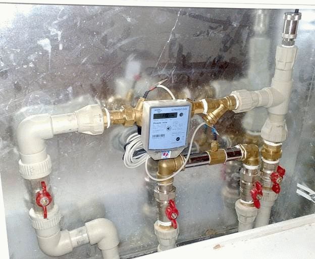
Consumption can be determined using heat meters. Heat meters can be of two types:
- Wing counters. Such devices are used to account for thermal energy, as well as the consumption of hot water. The difference between such meters and cold water metering devices is the material from which the impeller is made. In such devices, it is most resistant to high temperatures. The principle of operation is similar for two devices:
- The rotation of the impeller is transmitted to the accounting device;
- The impeller begins to rotate due to the movement of the working fluid;
- The transfer is made without direct interaction, but with the help of a permanent magnet.
Such devices have a simple design, but their response threshold is low.And also they have reliable protection against distortion of indications. With the help of an anti-magnetic screen, the impeller is prevented from braking by an external magnetic field.
- Devices with a recorder of differences. Such meters operate according to Bernoulli's law, which states that the speed of a liquid or gas flow is inversely proportional to its static movement. If the pressure is recorded by two sensors, it is easy to determine the flow in real time. The counter implies electronics in the design device. Almost all models provide information on the flow and temperature of the working fluid, as well as determine the consumption of thermal energy. You can set the operation manually using a PC. You can connect the device to a PC through the port.
Many residents are wondering how to calculate the amount of Gcal for heating in an open heating system, in which selection for hot water is possible. Pressure sensors are installed on the return pipe and the supply pipe at the same time. The difference that will be in the flow rate of the working fluid will show the amount of warm water that was spent for domestic needs.
Heat load schedule
To establish an economical
mode of operation of the heating
equipment, selection of the most optimal
coolant parameters it is necessary
know the duration of the system
heat supply under various modes
during a year. For this purpose, they build
heat duration charts
loads (Rossander plots).
Plot method
duration of seasonal heat
load is shown in fig. 4. Construction
conducted in four quadrants. In the left
upper quadrant graphs are plotted
outside temperature
tH,
heat load
heating Q,
ventilation QBand total seasonal
loads (Q
+ p c
during the heating season outdoor
temperatures tn,
equal to or below this temperature.
In the lower right quadrant
a straight line is drawn at an angle of 45° to
vertical and horizontal axes,
used to transfer values
scales P from
lower left quadrant to upper
right quadrant. Duration Graph
thermal load 5 is built for
different outside temperatures tnby intersection points
dashed lines defining thermal
load and standing time
loads equal to or greater than this.
Area under the curve 5
duration
heat load is equal to heat consumption
for heating and ventilation for heating
Q seasonWithyear.

Rice. 4. Plotting
duration of seasonal heat
loads
In the event that the heating
or ventilation load changes
by hours of the day or days of the week,
e.g. when during non-working hours
industrial enterprises are transferred
for standby heating or ventilation
industrial enterprises works
non-round the clock, three
heat flow curves: one (usually
solid line) based on average
at a given outside flow temperature
heat per week for heating and
ventilation; two (usually dashed)
based on the maximum and minimum
heating and ventilation loads
the same outdoor temperature tH.
Such a construction
shown in fig. 5.

Rice. 5. Integral graph
the total load of the area
a — Q= f(tn);
b —
heat duration chart
loads; 1 - average hourly per week
total load; 2
- maximum hourly
total load; 3
- minimum hourly
total load
Annual heat consumption per
heating can be calculated from a small
error without accurate accounting
outdoor temperature repeatability
air for the heating season, taking
average heat consumption for heating
season equal to 50% of heat consumption for
heating at the calculated outdoor
temperature tbut.
If the annual
heat consumption for heating, then, knowing
duration of the heating season,
it is easy to determine the average heat consumption.
Maximum heat consumption for heating
possible for approximate calculations
take equal to twice the average
consumption.
16
Option 3
We have the last option left, during which we will consider the situation when there is no heat energy meter on the house. The calculation, as in previous cases, will be carried out in two categories (thermal energy consumption for an apartment and ONE).
We will derive the amount for heating using formulas No. 1 and No. 2 (rules on the procedure for calculating thermal energy, taking into account the readings of individual meters or in accordance with the established standards for residential premises in gcal).
Calculation 1
- 1.3 gcal - readings of an individual meter;
- 1 400 rubles - approved rate.
- 0.025 gcal - standard indicator of heat consumption per 1 m? living area;
- 70 m? - the total area of the apartment;
- 1 400 rubles - approved rate.
As in the second option, the payment will depend on whether your housing is equipped with an individual heat meter. Now it is necessary to find out the amount of heat energy that was spent on general house needs, and this must be done according to formula No. 15 (volume of service for one unit) and No. 10 (amount for heating).
Calculation 2
Formula No. 15: 0.025 x 150 x 70 / 7000 \u003d 0.0375 gcal, where:
- 0.025 gcal - standard indicator of heat consumption per 1 m? living area;
- 100 m? - the amount of the area of \u200b\u200bpremises intended for general house needs;
- 70 m? - the total area of the apartment;
- 7,000 m? - total area (all residential and non-residential premises).
- 0.0375 - volume of heat (ONE);
- 1400 r. - approved rate.
As a result of the calculations, we found out that the full payment for heating will be:
- 1820 + 52.5 \u003d 1872.5 rubles. - with individual counter.
- 2450 + 52.5 \u003d 2,502.5 rubles. – without individual counter.
In the above calculations of payments for heating, data on the footage of the apartment, house, as well as on the meter indicators, which may differ significantly from those that you have, were used. All you need to do is plug your values into the formula and make the final calculation.
How to calculate the consumed thermal energy
If for one reason or another there is no heat meter, then the following formula must be used to calculate the heat energy:
Let's take a look at what these conventions mean.
1. V denotes the amount of hot water consumed, which can be calculated either in cubic meters or in tons.
2. T1 is the temperature indicator of the hottest water (traditionally measured in the usual degrees Celsius). In this case, it is preferable to use exactly the temperature that is observed at a certain operating pressure. By the way, the indicator even has a special name - this is enthalpy. But if the required sensor is not available, then the temperature regime that is extremely close to this enthalpy can be taken as the basis. In most cases, the average is about 60-65 degrees.
3. T2 in the above formula also indicates the temperature, but already cold water. Due to the fact that it is rather difficult to get into the cold water main, constant values are used as this value, which can change depending on the climatic conditions on the street. So, in winter, when the heating season is in full swing, this figure is 5 degrees, and in summer, with the heating turned off, 15 degrees.
4. As for 1000, this is the standard coefficient used in the formula in order to get the result already in gigacalories. It will be more accurate than if calories were used.
5. Finally, Q is the total amount of thermal energy.
As you can see, there is nothing complicated here, so we move on.If the heating circuit is of a closed type (and this is more convenient from an operational point of view), then the calculations must be made in a slightly different way. The formula that should be used for a building with a closed heating system should already look like this:
Now, respectively, to decryption.
1. V1 denotes the flow rate of the working fluid in the supply pipeline (not only water, but also steam can act as a source of thermal energy, which is typical).
2. V2 is the flow rate of the working fluid in the "return" pipeline.
3. T is an indicator of the temperature of the cold liquid.
4. T1 - water temperature in the supply pipeline.
5. T2 - temperature indicator, which is observed at the outlet.
6. And, finally, Q is all the same amount of thermal energy.
It is also worth noting that the calculation of Gcal for heating in this case is based on several designations:
- thermal energy that entered the system (measured in calories);
- temperature indicator during the removal of the working fluid through the "return" pipeline.
—
CAUTION 1
rеÑодика Ñеплового п¿ Ð Ð Ð Ð Ð Ð Ð Ð Ð Ð Ð Ð Ð Ð Ð Ð Ð Ð Ð Ð Ð Ð Ð Ð Ð Ð Ð Ð Ð Ð Ð Ð Ð Ð Ð Ð Ð Ð Ð Ð Ð ññ 100% пÑедположение Ð Ð Ð Ð Ð Ð Ð Ð Ð Ð Ð Ð Ð Ð Ð Ð Ð Ð Ð Ð ÐμÐ Ð Ð Ð Ð ÐμÐ Ð Ð Ð Ð Ð Ð ÐμÐ Ð Ð Ð Ð Ð Ð Ð Ð Ð Ð ² Ð ÐμÐðÐðÐ Ð Ð Ð Ð Ð Ð · Ð Ð Ð Ð Ð Ð · Ð Ð Ð Ð Ð Ð · Ð Ð Ð Ð Ð Ð Ð Ð Ð Ð Ð Ð Ð Ð Ð Ð Ð Ð Ð Ð Ð Ð Ð Ð Ð Ð Ð Ð Ð Ð Ð Ð Ð Ð Ð Ð Ð Ð Ð Ð Ð Ð Ð Ð Ð Ð Ð Ð Ð μl .
a
rеÑодика Ñеплового пР° ÑовÑÑ Ð¸ воÐ'огÑÐμйнÑÑ ÐºÐ¾ÑÐ »Ð¾Ð² ÑÐ ° Ð · Ð ± иÑÐ ° нР° оÑÐ'Ðμл ÑнÑÐμ ÑÐ ° ÑÑи, помÐμÑÐμннÑÐμ в ÑооÑвÐμÑÑÑвÑÑÑиÐμ гР»Ð ° вÑ.
a
ÐеÑодики. R. Ðлин-ковÑм, Ð. R. Ð ¢ Ð ° йÑÐμм и Ð'ÑÑгими, вÑÐ »ÐμÐ'ÑÑвиÐμ Ð¸Ñ Ð¿ÑоÑÑоÑÑ Ð¿Ð¾Ð» ÑÑиР»Ð¸ Ð ± ол ÑÑоÐμ ÑÐ ° ÑпÑоÑÑÑÐ ° нÐμни е.
a
rеÑодика Ñеплового LOOK OUT.
a
ÐеÑодика пÑиведена в Ñазд.
a
back оÑвÐμÑÐμнР° в Ð »Ð¸ÑÐμÑÐ ° ÑÑÑÐμ, Ð ° поÑÐ¾Ð¼Ñ Ð¾Ð³ÑÐ ° ниÑимÑÑ Ð¿ÑивÐμÐ'ÐμниÐμм оконÑÐ ° ÑÐμл ÑнÑÑ ÑÐ ° ÑÑÐμÑнÑÑ ÑоÑмÑÐ »(Ð ± ÑквÐμннÑÐμ оР± оР· наÑÐµÐ½Ð¸Ñ Ñм. на Ñиг.
a
|
опеÑеÑное ÑеÑение мÑÑелÑной пеÑи. a |
ÐеÑодика Ñеплового Ð Ð Ð ° Ð Ð Ð Ð Ð Ð Ð Ð Ð Ð Ð Ð Ð Ð Ð Ð ² â Ð Ð Ð Ð Ð Ð Ð Ð Ð Ð Ð Ð Ð Ð Ð Ð Ð Ð Ð Ð Ð Ð Ð Ð Ð Ð Ð Ð Ð Ð Ð Ð Ð Ð Ð Ð Ð Ð Ð Ð Ð Ð Ð Ð Ð Ð Ð Ð Ð Ð Ð Ð Ð Ð Ð Ð Ð Ð Ðμ п Ð Ð Ð Ð Ð Ð Ð Ð Ð Ð Ð Ð Ð Ð Ð Ð Ð Ð Ð Ð Ð Ð Ð Ð Ð Ð Ð Ð Ð Ð Ð Ð Ð Ð Ð Ð Ð ñ ñ Ð Ð Ð Ð Ð ñ ñ ñ ¾ Ð Ð ñññμμð Ð Ð Ð ñðñμ½½ºº Рмññμμμ »» ñ.
a
ÐеÑодика Ñеплового Ð Ðμñ Ð Ð Ð Ð ÐμÐÐ Ð Ð Ð Ð δÐðÐ Ð Ð Ð δÐ Ð Ð Ð α РРРРРРРо РРРо
a
еÑодика Ñеплового в ÑÑом ÑÑом ÑлÑÑае ÑводиÑÑÑÑÑÑÑк кедÑÑÑим опеÑаÑиÑм.
a
Ð Ð Ð Ð Ð Ð Ð Ð Ð Ð Ð Ð Ð Ð Ð Ð Ð Ð Ð Ð Ð Ð Ð Ð Ð Ð Ð Ð Ð Ð Ð Ð Ð Ð Ð Ð Ð Ð ° Ð Ð Ð Ð Ð, Ð ° Ð Ð Ð Ð Ð Ð Ð Ð Ð Ð Ð Ð Ð Ð Ð Ð Ð Ð Ð Ð Ð Ð Ð Ð Ð Ð Ð Ð Ð Ð Ð Ð Ð Ð Ð Ð Ð Ð Ð Ð Ð Ð Ð Ð Ð Ð Ð Ð Ð Ð Ð Ð Ð Ð ñ Ð Ð Ð Ð Ð Ð Ð Ð Ð Ð Ð Ð Ð Ð Ð Ð Ð Ð Ð Ð Ð Ð Ð Ð Ð Ð Ð Ð Ð Ð Ð Ð Ð Ð Ð Ð Ð Ð Ð Ð Ð Ð Ð Ð Ð Ð Ð Ð Ð Ð Ð Ð Ð Ð Ð Ð Ð Ð Ð Ð Ð Ð Ð Ð Ð Ð Ð Ð Ð Ð Ð Ð Ð Ð Ð Ð Ð Ð Ð Ð Ð Ð Ð Ð Ð ñ »Ð Ð Ð ² РРРРРРРРРРРРРРРРРРРРРРРРРРРРРРРо
a
|
Ðñð¸ññ½¸ððððð μðð½½ðððÐðÐðÐμμÐ𺺺ÐðÐðÐμкºðμÐμÐμÐμμμμμÐμн½μμμμннн½¹ Ðð ÐðÐðÐðÐðÐðÐððð¹ððððððð a |
ÐÐμÑоÐ'икР° ÑÐμпР»Ð¾Ð²Ð¾Ð³Ð¾ ÑÐ ° ÑÑÐμÑÐ ° иÑпР° ÑиÑÐμл Ðμй ÑÐ ° Ð · Ð »Ð¸ÑнÑÑ ÐºÐ¾Ð½ÑÑÑÑкÑий оÑвеÑен а во оÑоÑом Ñазделе гл.
a
Ð Ð Ð Ð Ð Ð Ð Ð Ð Ð Ð Ð Ð Ð Ð Ð Ð Ð Ð Ð Ð Ð Ð Ð Ð Ð Ð Ð Ð ÐμÐ Ð ÐμÐ Ð Ð ÐμÐ Ð Ð ÐμÐ Ð ² ñ Ð Ð Ð Ð Ð Ð Ð Ð Ð Ð Ð Ð Ð Ð Ð Ð Ð Ð Ð Ð Ð Ð Ð Ð Ð Ð Ð Ð Ð Ð Ð Ð Ð Ð Ð Ð Ð Ð Ð Ð Ð Ð Ð Ð Ð Ð Ð Ð Ð Ð Ð Ð Ð Ð Ð Ð Ð Ð Ð Ð Ð Ð Ð Ð Ð Ð Ð Ð Ð Ð Ð Ð Ð ° Ð Ð Ð Ð Ð Ð Ð , но
a
|
Run. ñðμμð¸ññññ ñ'ðððññ² Ð Ð Ð Ð Ð Ð Ð Ð Ð Ð Ð Ð Ð Ð Ð Ð Ð Ð Ð Ð Ð Ð a |
Other ways to calculate the amount of heat
It is possible to calculate the amount of heat entering the heating system in other ways.
The calculation formula for heating in this case may differ slightly from the above and have two options:
- Q = ((V1 * (T1 - T2)) + (V1 - V2) * (T2 - T)) / 1000.
- Q = ((V2 * (T1 - T2)) + (V1 - V2) * (T1 - T)) / 1000.
All values of the variables in these formulas are the same as before.
Based on this, it is safe to say that the calculation of kilowatts of heating can be done on your own. However, do not forget about consulting with special organizations responsible for supplying heat to dwellings, since their principles and calculation system can be completely different and consist of a completely different set of measures.
Having decided to design a so-called “warm floor” system in a private house, you need to be prepared for the fact that the procedure for calculating the volume of heat will be much more difficult, since in this case it is necessary to take into account not only the features of the heating circuit, but also provide for the parameters of the electrical network, from which and the floor will be heated. At the same time, the organizations responsible for monitoring such installation work will be completely different.
Many owners often face the problem of converting the required number of kilocalories into kilowatts, which is due to the use of many auxiliary aids of measuring units in the international system called "Ci". Here you need to remember that the coefficient that converts kilocalories to kilowatts will be 850, that is, in simpler terms, 1 kW is 850 kcal. This calculation procedure is much simpler, since it will not be difficult to calculate the required amount of gigacalories - the prefix "giga" means "million", therefore, 1 gigacalorie - 1 million calories.
In order to avoid errors in calculations, it is important to remember that absolutely all modern heat meters have some error, and often within acceptable limits. The calculation of such an error can also be done independently using the following formula: R = (V1 - V2) / (V1 + V2) * 100, where R is the error of the common house heating meter
V1 and V2 are the parameters of water consumption in the system already mentioned above, and 100 is the coefficient responsible for converting the obtained value into a percentage. In accordance with operating standards, the maximum allowable error can be 2%, but usually this figure in modern devices does not exceed 1%.
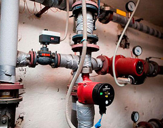
Heat meter calculation
Calculation of the heat meter consists in choosing the size of the flow meter. Many mistakenly believe that the diameter of the flowmeter must match the diameter of the pipe on which it is installed.
The diameter of the heat meter flow meter should be selected based on its flow characteristics.
- Qmin — minimum flow, m³/h
- Qt - transition flow, m³/h
- Qn - nominal flow, m³/h
- Qmax — maximum allowable flow, m³/h
0 - Qmin - the error is not standardized - long-term operation is allowed.
Qmin - Qt - error not more than 5% - long-term operation is allowed.
Qt – Qn (Qmin – Qn for flowmeters of the second class for which the Qt value is not specified) – error not more than 3% – continuous operation is allowed.
Qn - Qmax - error no more than 3% - work is allowed no more than 1 hour per day.
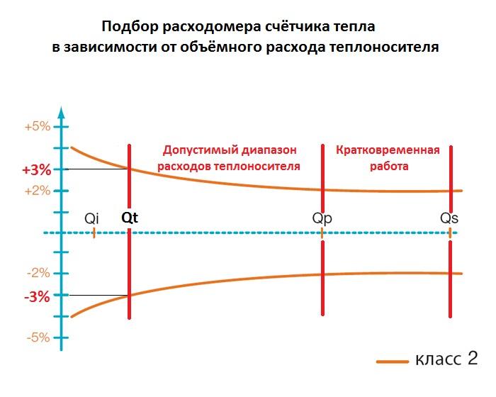
It is recommended to select flow meters of heat meters in such a way that the calculated flow rate falls within the range from Qt to Qn, and for flow meters of the second class for which the Qt value is not specified, in the flow range from Qmin to Qn.
In this case, one should take into account the possibility of reducing the coolant flow through the heat meter, associated with the operation of control valves and the possibility of increasing the flow through the heat meter, associated with the instability of the temperature and hydraulic conditions of the heating network. It is recommended by regulatory documents to select a heat meter with the closest value of the nominal flow rate Qn to the calculated flow rate of the coolant. Such an approach to the choice of a heat meter practically excludes the possibility of increasing the coolant flow rate above the calculated value, which quite often has to be done in real heat supply conditions.
The above algorithm displays a list of heat meters that, with the declared accuracy, will be able to take into account the flow rate one and a half times higher than the calculated one and three times less than the calculated flow rate. The heat meter chosen in this way will allow, if necessary, to increase the consumption at the facility by one and a half times and reduce it by three times.