Method 1
fire trucksworldsleevetrunks19 mm
| Head in the network, m | Type of water supply network | Water return of the network, l / s, with a pipe diameter, mm | |||||||||||||
| 100 | 125 | 150 | 200 | 250 | 300 | 350 | |||||||||
| 10 | dead end | 10 | — | 20 | — | 25 | — | 30 | — | 40 | — | 55 | — | 65 | — |
| Ring | — | 25 | — | 40 | — | 55 | — | 65 | — | 85 | — | 115 | — | 130 | |
| 20 | dead end | 14 | — | 25 | — | 30 | — | 45 | — | 55 | — | 80 | — | 90 | — |
| Ring | — | 30 | — | 60 | — | 70 | — | 90 | — | 115 | — | 170 | — | 195 | |
| 30 | dead end | 17 | — | 35 | — | 40 | — | 55 | — | 70 | — | 95 | — | 110 | — |
| Ring | — | 40 | — | 70 | — | 80 | — | 110 | — | 145 | — | 205 | — | 235 | |
| 40 | dead end | 21 | — | 40 | — | 45 | — | 60 | — | 80 | — | 110 | — | 140 | — |
| Ring | — | 45 | — | 85 | — | 95 | — | 130 | — | 185 | — | 235 | — | 280 | |
| 50 | dead end | 24 | — | 45 | — | 50 | — | 70 | — | 90 | — | 120 | — | 160 | — |
| Ring | — | 50 | — | 90 | — | 105 | — | 145 | — | 200 | — | 265 | — | 325 | |
| 60 | dead end | 26 | — | 47 | — | 55 | — | 80 | — | 110 | — | 140 | — | 190 | — |
| Ring | — | 52 | — | 95 | — | ON | — | 163 | — | 225 | — | 290 | — | 380 | |
| 70 | dead end | 29 | — | 50 | — | 65 | — | 90 | — | 125 | — | 160 | — | 210 | — |
| Ring | — | 58 | — | 105 | — | 130 | — | 182 | — | 255 | — | 330 | — | 440 | |
| 80 | dead end | 32 | — | 55 | — | 70 | — | 100 | — | 140 | — | 180 | — | 250 | — |
| Ring | — | 64 | — | 115 | — | 140 | — | 205 | — | 287 | — | 370 | — | 500 |
pump nozzle hose line nozzle compact jet barrels "B" "A"
| Head at the trunk, m | Water consumption, l / s, from the barrel with nozzle diameter, mm | ||||||
| 13 | 19 | 25 | 28 | 32 | 38 | 50 | |
| 20 | 2,7 | 5,4 | 9,7 | 12,0 | 16,0 | 22,0 | 39,0 |
| 30 | 3,2 | 6,4 | 11,8 | 15,0 | 20,0 | 28,0 | 48,0 |
| 40 | 3,7 | 7,4 | 13,6 | 17,0 | 23,0 | 32,0 | 55,0 |
| 50 | 4,1 | 8,2 | 15,3 | 19,0 | 25,0 | 35,0 | 61,0 |
| 60 | 4,5 | 9,0 | 16,7 | 21,0 | 28,0 | 38,0 | 67,0 |
| 70 | — | — | 18,1 | 23,0 | 30,0 | 42,0 | 73,0 |
| 80 | — | — | — | — | — | 45,0 | 78,0 |
booster pumps
Nominal passage of the fitting and shut-off valves for draining water from sectioned sections of water heating networks or condensate from condensate networks
|
Conditional |
Before |
80-125 |
150 |
200-250 |
300 |
500 |
600 |
800 |
1000-1400 |
|
Conditional |
25 |
40 |
50 |
80 |
100 |
150 |
200 |
250 |
300 |
Appendix
10*
Recommended
CONDITIONAL PASSIONS OF FITTINGS AND FITTINGS
FOR AIR EXHAUST IN HYDROPNEUMATIC
FLUSHING, DRAINING AND COMPRESSED
AIR*
Table 1
Nominal passage of the fitting and shut-off
air outlet fittings
|
Conditional |
25-80 |
100-150 |
200-300 |
350-400 |
500-700 |
800-1200 |
1400 |
|
Conditional |
15 |
20 |
25 |
32 |
40 |
50 |
65 |
table 2
Nominal passage of fitting and armature
for draining water and supplying compressed air
|
Conditional |
50- 80 |
100-150 |
200-250 |
300-400 |
500-600 |
700- 900 |
1000-1400 |
|
Conditional |
40 |
80 |
100 |
200 |
250 |
300 |
400 |
|
Same for |
25 |
40 |
40 |
50 |
80 |
80 |
100 |
|
Conditional |
50 |
80 |
150 |
200 |
300 |
400 |
500 |
APPENDIX 11
Recommended
CONDITIONAL PASSES OF FITTINGS AND SHUT-OFF
FITTINGS FOR START-UP AND CONTINUOUS
STEAM DRAINAGE
Table 1
Nominal passage of the fitting and shut-off
fittings for start-up drainage
steam pipelines
|
Conditional |
Before |
80-125 |
150 |
200-250 |
300-400 |
500-600 |
700-800 |
900-1000 |
1200 |
|
Conditional |
25 |
32 |
40 |
50 |
80 |
100 |
150 |
150 |
200 |
table 2
Nominal nozzle diameter for permanent
steam drainage
|
Conditional |
25-40 |
50-65 |
80 |
100-125 |
150 |
200-250 |
300-350 |
400 |
500-600 |
700-800 |
900-1200 |
|
Conditional |
20 |
32 |
40 |
50 |
80 |
100 |
150 |
200 |
250 |
300 |
350 |
|
Conditional |
15 |
25 |
32 |
32 |
40 |
50 |
80 |
80 |
100 |
150 |
150 |
Applications 12—19exclude.
APPENDIX 20
Reference
TYPES OF COATINGS FOR EXTERNAL PROTECTION
SURFACES OF PIPES OF HEAT NETWORKS FROM
CORROSION
|
Way |
Temperature |
Types of coatings |
Total thickness |
Regulatory |
|
1. Aboveground, |
Regardless |
Oil-bituminous |
0,15-0,2 |
OST 6-10-426-79 GOST 25129-82 |
|
outside |
300 |
Metallization |
0,25-0,3 |
GOST |
|
2. Underground |
300 |
Glass enamel |
TU VNIIST |
|
|
in impassable |
105T in three |
0,5-0,6 |
||
|
channels |
64/64 in three |
0,5-0,6 |
||
|
13-111 at three |
0,5-0,6 |
|||
|
596 into one |
0,5 |
|||
|
180 |
Organosilicate |
0,25-0,3 |
TU84-725-83 |
|
|
With |
0,45 |
|||
|
150 |
Isol at two |
5-6 |
GOST 10296-79 THAT |
|
|
Epoxy |
0,35-0,4 |
GOST 10277-90 TU6-10-1243-72 |
||
|
Metallization |
025-0,3 |
GOST 7871-75 |
||
|
3. Channelless |
300 180 150 |
Glass enamel - according to clause 2 of the application
Protective - according to clause 2 of the application, except |
||
|
Notes: 1. If the manufacturers
2.When using thermal insulation
3. Aluminum plating |
APPENDIX 21
Recommended
Drainage and purge system of steam pipelines
The drainage and purge system of steam pipelines should provide:
- Purge of the steam pipeline - removal of the resulting condensate and wet steam from the heated section of the steam pipeline before putting it into operation.
- Emptying - removal of condensed steam from the off section of the steam pipeline.
- Permanent drainage - continuous removal of condensate from the working section of the steam pipeline if condensate forms in it.
- Removal of air from steam pipelines when filling them with water for the purpose of hydraulic testing.
- Collection and use of condensate and heat from drains and blowdowns.
drainage fittings on a temporary network water pipeline
External water supply networks
The planned sites provide for above-ground laying of utility and drinking water pipelines, industrial and fire-fighting water pipelines, underground water pipelines and a foam concentrate solution pipeline on low supports, when crossing roads - on high supports (at least 5.0 m from the top of the road to the bottom of the supporting structure, clause 6.25b of SP 18.13330.2011). The distances from the water supply to communications laid jointly on the overpass are taken in accordance with Section 6 of SP 18.13330.2011.
Compensation of thermal elongation of pipelines is solved due to the angles of rotation of the route and U-shaped thermal elongation compensators.
In accordance with paragraph 3 of Art. 18 of Federal Law No. 384, to ensure the safety of buildings and structures on the site, emergency protection of engineering and technical support systems is provided. To do this, in the event of an emergency or repair to turn off the water supply on external networks, shut-off valves are provided.
According to clause 11.10, note SP 31.13330.2012, on the ring fire water supply, the network is divided into repair sections (disconnecting no more than 5 fire hydrant units).
The pipeline of the foaming agent solution is designed dry-pipe; after a fire, the pipeline is freed from residues and washed with water.
Pipelines are designed with a slope of at least 0.002, which ensures their emptying. Air vents are installed at the highest points of the pipelines, and downcomers are installed at the lowest points. In working condition, the valves on the drains and air vents must be closed and muffled. Drainage of water from the pipelines is provided for in the nearest well of gravity sewerage, no more than 2 hours (clause 11.14 of SP 31.13330.2012).
Anti-corrosion coating of aboveground pipelines is provided by the composition of organo-silicate OS-12-03 according to TU 84-725-83 (in 2 layers).
When laying the pipelines of the production and fire-fighting water supply and the foam concentrate solution in the square of the tank farm, protection of the pipes from the heat of a possible fire is used:
- primer GF-021 according to GOST 25129-82 (1 layer);
- fire-retardant coating "Phoenix STS" according to TU 5768-005-66959951-2011 (1 layer).
As a vapor barrier layer, a polyethylene film 0.2 mm thick is used in accordance with GOST 10354-82 grade C in two layers. For gluing the seams of the vapor barrier film, a polyethylene tape with an adhesive layer is used according to GOST 20477-86 grade A, 0.18 mm thick, 50 mm wide.
The pipelines of the utility and drinking water supply, the production and fire-fighting water supply and the underground water supply are provided in thermal insulation with an electric heating device.
Fittings, flange connections, pipeline parts are thermally insulated with the same materials as pipelines.
Thermal insulation of pipes is provided by mats made of mineral wool GOST 21880-2011.The thickness of the mats is calculated according to the standard heat flux density and is accepted taking into account the compaction factor during installation (in accordance with Appendix B of SP 61.13330.2012). The thickness of the insulating layer for pipelines with a diameter of up to 89 mm inclusive is 60 mm. Compaction coefficient Kc = 1.2.
The cover layer is steel, thin-sheet galvanized with a thickness of 0.5 mm according to GOST 14918-80.
Before applying the anti-corrosion coating, the surface of the pipes is preliminarily degreased, cleaned of rust and scale to degree 2, and dusted in accordance with GOST 9.402-2004.
Installation, welding and control of welded joints, testing of pipelines shall be carried out in accordance with the requirements of SNiP 3.05.04-85*.
fittings
79. Armature
steam and hot water pipelines
be installed in places accessible
for convenient and safe maintenance
and repair. Where necessary, should
be arranged fixed stairs and
sites in accordance with the design
documentation. Applicable
mobile platforms and attachments
ladders for rarely used (less often
once a month) fittings, access to
the management of which is necessary for
shutdown of the pipeline section in
repair and connect it after repair.
Attachments are not allowed
ladders for the repair of fittings with its
disassembly and dismantling.
Installable
cast iron fittings for steam pipelines
and hot water must be protected from
bending stresses.
80. Apply
shut-off valve as a control
not allowed.
81. In the project
steam lines with an inner diameter of 150
mm or more and a steam temperature of 300 °C and
installation locations must be indicated above
displacement indicators and calculated
the values of their movements. To the pointers
movement should be provided
Free access.
82. Installation
shutoff valves on heating networks
provides for:
a) for all
pipelines of outputs of heat networks
from heat sources, regardless of
coolant parameters;
b) on pipelines
water networks with a nominal diameter of 100 mm
and more at a distance of no more than 1000 meters
(sectional valves) with device
jumpers between supply and return
pipelines;
c) in water and
steam heating networks in nodes on
branch pipelines conditional
with a diameter of more than 100 mm, as well as in knots
on branch pipelines to individual
buildings, regardless of diameter
pipeline;
d) on condensate pipelines
at the inlet to the condensate collection tank.
83. Valves and
valves with a diameter of 500 mm or more are equipped
electric drive. For above-ground laying
heating networks gate valves with electric drives
installed indoors or concluded
in casings protecting fittings and
electric drive against atmospheric precipitation
and excluding access to them by outsiders
persons.
84. All pipelines
regardless of the transported product
must have drains to drain water
after hydraulic test and
air vents at the top of pipelines
to remove gas. Locations
and design of air and drainage
pipeline devices are installed
project documentation.
85. Technological
pipelines in which
product condensation, must have
drainage devices for continuous
removal of liquid.
Continuous retraction
condensate is required for steam lines
saturated steam and for dead ends
superheated steam pipelines.
For steam thermal
networks continuous removal of condensate to
the lowest points of the route is required
regardless of the state of the steam.
Construction, type
and installation sites for drainage devices
determined by the project.
86. At the bottom
pipelines of water heating networks
and condensate pipelines, as well as sectioned
sections mount a fitting with a shut-off
fittings for draining water (drainage
devices).
87. From steam pipelines
heating networks at low points and before
vertical lifts should be
continuous condensate drain
through condensers.
In the same places
as well as on straight sections of steam pipelines
after 400 - 500 meters with passing and through
200 - 300 meters on the opposite slope
install a starter drain
steam pipelines.
88. For draining water
from pipelines of water heating networks
provide waste pits,
separate from the channel
pipelines, with water drainage into systems
sewerage.
89. All plots
steam lines, which can be
shut off by locking devices, for
the possibility of their heating and purging,
must be provided at the end points
fitting with a valve, and at pressure
over 2.2 MPa - with a fitting and two
in series
valves: shut-off and control.
Steam pipelines for pressure 20 MPa and above
must be provided with fittings with
shut-off valves in series
and control valves and throttle
puck. In cases of warming up the area
steam lines in both directions
purge must be provided with
both ends of the section.
Drainage device
should provide for the possibility
control over their work during warm-up
pipeline.
90. Bottom end
points of steam pipelines and their lower points
bends must be provided with a device
for purge.
91. On the water
heating networks with a diameter of 500 mm or more
at a pressure of 1.6 MPa or more, with a diameter
300 mm or more at a pressure of 2.5 MPa or more,
on steam networks with a diameter of 200 mm or more
at a pressure of 1.6 MPa or more for gate valves
and gates are provided by bypass
pipelines (bypasses) with shut-off
fittings.
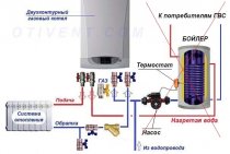
Reasons why air enters the system
Most often, air jams appear in the heating system after a long downtime, repair or replacement of any parts. Also, due to too rapid filling of the network with coolant, air bubbles form, so it must be filled slowly. After the initial filling of the liquid, air plugs always appear in the system. Since dissolved oxygen is present in the water, when heated, it begins to evaporate and rise to the highest places, slowing down the circulation of the coolant.
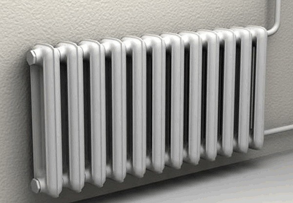
air in battery
In addition to noise and poor heating of radiators, the air in the heating system contributes to pipe corrosion and pressure surges in the network. It is especially dangerous for wet-type circulation pumps, since during operation their sliding rings require constant lubrication with coolant.
In order for the entire network to last as long as possible, all radiators, boilers, collectors and other places where the passage of air is difficult should be equipped with air vents. If, after venting the gases, the system still does not warm up properly, it is recommended to drain all the coolant in order to flush the pipes, since excessive contamination may be the cause of poor circulation.
https://youtube.com/watch?v=4MEtfcioyNE%3F
Navigation
-
2019/08/17 15:24 Obsidian updated the page Barrel A. 2019/08/17 15:24 Obsidian updated the Barrel B page. 2019/07/18 10:44 Aleksey updated the Linear speed of combustion propagation page. 2019/04/10 14:10 Obsidian updated the Siberian Fire and Rescue Academy page. 2019/01/23 15:56 Obsidian updated the GDZS Online Calculator page. 2019/01/23 09:32 Obsidian updated AIGS GraFiS page. 2018/12/04 11:01 Obsidian has updated the page Fire-extinguishing supplies. 2018/11/11 16:12 Obsidian updated the Path of Fire page. 2018/11/11 16:08 Obsidian updated the GDZS Online Calculator page. 2018/11/04 20:15 Obsidian updated the GDZS Online Calculator page. 2018/09/03 11:21 Obsidian has updated the Pumping Hose Systems page. 2018/08/27 09:34 Obsidian has updated the Fire Extinguishing in Buildings with Hinged Ventilated Facades page. 2018/07/31 16:54 Obsidian has updated the page Calculations of the parameters of work in RPE. 2018/07/31 15:00 Obsidian has updated the page Calculations of the parameters of work in RPE. 2018/07/24 09:26 Obsidian has updated the page Calculations of the parameters of work in RPE. 2018/07/17 14:46 Obsidian has updated the page Calculations of the parameters of work in RPE. 2018/06/19 20:56 Tor updated the Combined Fire Suppression Schedule page for changes in fire area, required and actual consumption of extinguishing agents over time. 2018/05/18 16:40 Obsidian updated the Firefighting Headquarters page. 2018/04/20 11:00 Obsidian updated the page Departmental awards of the EMERCOM of Russia. 2018/04/18 19:51 Obsidian updated the page Departmental awards of the EMERCOM of Russia. - Random Page
- New page
- All pages
- Categories
- Files
-
Pages that have links to this article
-
- Classification of fire equipment
- fire trucks
- fire hoses
- Sleeve lines
- Hand fire nozzles
- Barrel A
- Barrel B
Pages linked to in this article
Site search
Auto
As you can see from the name of this device, it works independently and does not require human intervention, as it automatically removes air from the network. The gas outlet valve is located on the top or side.
The automatic air vent consists of the following parts:
- frame;
- case cover;
- float;
- jet;
- holder;
- spool;
- spring;
- sealing ring of the valve and body;
- Cork.
Attention! Install the automatic air vent only in a vertical position. Otherwise, the device will start to leak.
The connecting threaded part of such an air vent can be straight or L-shaped (angular). Devices of the latter type are often installed on radiators instead of the Mayevsky crane.
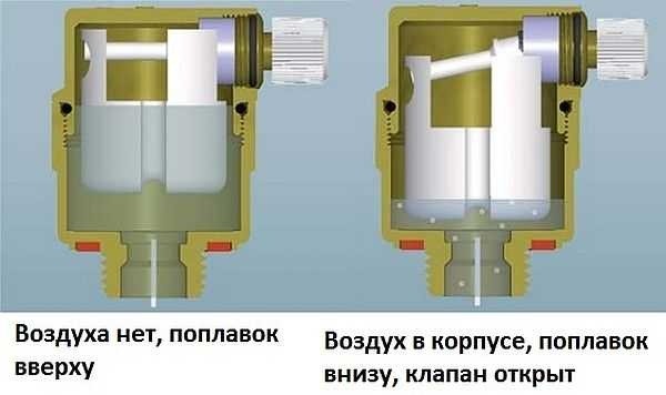
The principle of operation of an automatic air vent is as follows: air enters the upper part of the body, lowering the float and displacing water from the device. The float, descending, acts on the holder, which opens the valve, releasing air to the outside. Once all the gas is out, the water fills the body and lifts the float back up. At the same time, the holder closes the valve with an air outlet so that the coolant does not leak out.
Automatic type devices are highly responsive to the quality of the fluid in the heating system. To ensure that they last as long as possible without interruption, it is recommended to install cleaning filters.
Fittings of thermal networks
Rating: / 0
- Details
- Created on 06/29/2015 21:11
- Publication date
- Views: 2182
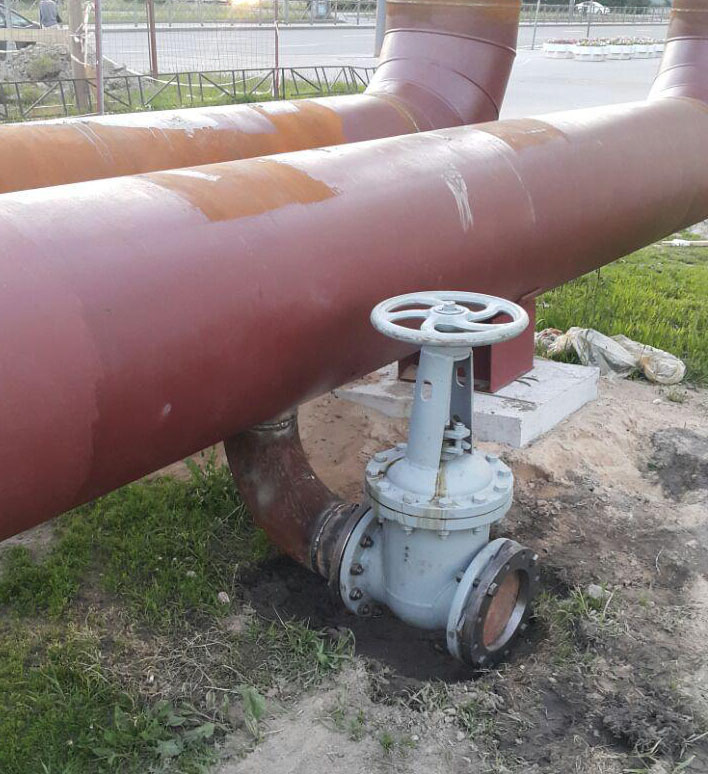
Modern residential buildings cannot be imagined without plumbing, which is a prerequisite for a comfortable stay for residents. All plumbing equipment, which includes water supply, sewerage and central heating systems, has both internal and external networks. External communications consist of the main, central highway and branches for direct connection to internal systems. The correct location and installation of plumbing equipment plays a big role in the normal functioning of all plumbing systems. In houses, it is necessary to lay the pipes of internal plumbing in such a way that they always have access. There are also established standards for laying external plumbing communications, which allow you to timely carry out the necessary prevention and repair of plumbing networks.
One of the types of external plumbing communications are heating networks that serve residential complexes. Through heating networks, hot water or steam is transported and distributed to end consumers. These are quite complex structures with a large branched network of pipelines. Naturally, in such networks, shut-off valves are needed that block or let the transported medium in a certain direction as needed.Without the presence of shut-off valves, the normal functioning of not only the heating main, but also any other pipelines is unthinkable. Each of the sections of the heating main can be blocked at any time in the event of an accident, and the supply of hot water can be stopped until the accident is completely eliminated. This is necessary for the safety of consumers, and also ensures the supply of warm water and heating to undamaged sections of the route so as not to disturb the bulk of consumers.
We can say that valves are an organic component and a type of pipelines, it includes various gate valves,
gates, valves, ball valves. Structurally, valves are made of anti-corrosion materials that can withstand high temperatures and pressures. For example, a stainless ball valve, as its name implies, is made of stainless steel and is able to serve for a long time, fully performing its functions. There are among these fittings and devices that regulate the flow of the medium through pipelines. These products include shut-off valves that regulate the flow of the transported medium over a wide range. The terms of normal operation of shut-off valves reach 30 years, they are simple, reliable and do not require special maintenance.
Devices for signaling the extreme positions of the shut-off valve body
Contact, non-contact (inductive and transformer) sensors and sensors on the MUK are used to signal the extreme positions of the shut-off valve.
The first two types - separate finished products with a certain degree of autonomy - are designed to control the positions of the valves "Open" and "Closed". They have a number of input parameters consistent with the armature mechanism: connection point, stroke of the rod, mandatory and permissible clamping, differential, impact force.
The armature, in turn, has a sensor installation and adjustment unit.
Signaling devices that have only translational movement (armature with one- and two-cavity servomotor, etc.) are called mounted.
The operation of the node is as follows. The shaft receives rotation from the armature drive. The shaft is rigidly connected by a coupling with two adjusting screws. When the shaft is rotated, the clutch turns the lever around the axis with an adjusting screw. The lever acts on a rod rigidly connected to the sensor rod. The return of the sensor rod, rod and lever to its original position is carried out by the return spring of the sensor and the return spring. The assembly is adjusted in the following sequence
The valve is set to the "Closed" position.
The sensor is connected to a power source and an indicating device (light bulb). The adjusting screw is screwed in until the "Closed" signal appears. In this position, with the cover removed, the size is measured, then the screw is turned until the desired size is obtained and stops, after which the size is checked.
The armature is set to the "Open" position.
The adjusting screw is screwed in until the “open” signal appears. In this position, the size is measured, the adjusting screw is turned until the desired size is obtained. Then the adjusting screw is locked, after which the size is checked.