Delving into the topic
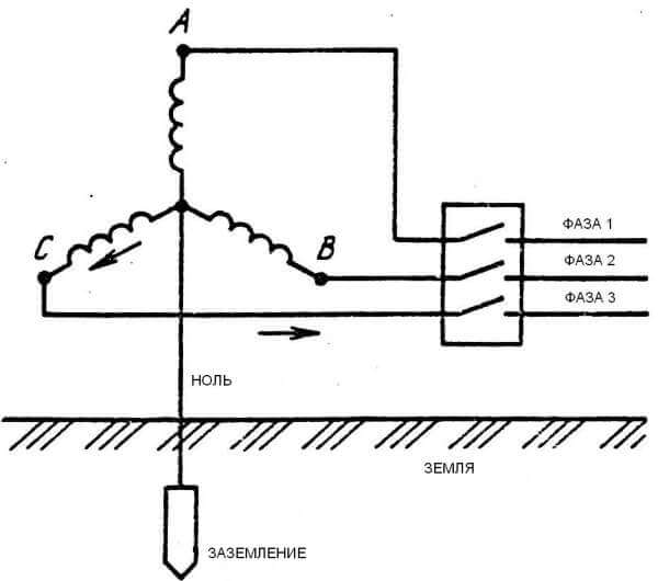
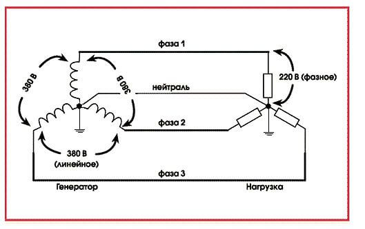
Consumers are fed from the low voltage windings of a step-down transformer, which is the most important component of the operation of a transformer substation. The connection of the substation and subscribers is as follows: a common conductor is supplied to the consumers, extending from the connection point of the transformer windings, called the neutral, along with three conductors, which are the conclusions of the remaining ends of the windings. In simple terms, each of these three conductors is a phase, and the common one is zero.
Between the phases in a three-phase power system, a voltage occurs, called linear. Its nominal value is 380 V. Let's define the phase voltage - this is the voltage between zero and one of the phases. The nominal value of the phase voltage is 220 V.
An electrical power system in which zero is connected to ground is called a "hard-earthed neutral system." To make it extremely clear even for a beginner in electrical engineering: “ground” in the electric power industry means grounding.
The physical meaning of a solidly grounded neutral is as follows: the windings in the transformer are connected in a "star", while the neutral is grounded. Zero acts as a combined neutral conductor (PEN). This type of connection to the ground is typical for residential buildings belonging to the Soviet construction. Here, in the entrances, the electrical panel on each floor is simply grounded, and a separate connection to the ground is not provided.
It is important to know that it is very dangerous to connect the protective and neutral conductor to the shield body at the same time, because there is a possibility that the operating current will pass through zero and its potential will deviate from zero, which means the possibility of electric shock
The same three phases, as well as separated neutral and protective conductors, are provided from the transformer substation to houses belonging to a later construction. Electric current passes through the working conductor, and the purpose of the protective wire is to connect the conductive parts to the ground loop available at the substation. In this case, in the electrical panels on each floor there is a separate bus for separate connection of the phase, zero and ground. The ground bus has a metal connection with the shield body.
It is known that the load on subscribers should be distributed evenly over all phases. However, it is not possible to predict in advance what power will be consumed by a particular subscriber. Due to the fact that the load current is different in each individual phase, a neutral displacement appears. As a result, there is a potential difference between zero and ground. In the case when the cross section of the neutral conductor is insufficient, the potential difference becomes even greater. If the connection with the neutral conductor is completely lost, then there is a high probability of emergency situations in which in phases loaded to the limit, the voltage approaches zero, and in unloaded ones, on the contrary, it tends to a value of 380 V. This circumstance leads to a complete breakdown of electrical equipment . At the same time, the body of electrical equipment is energized, dangerous to human health and life. The use of separated neutral and protective wires in this case will help to avoid such accidents and ensure the required level of safety and reliability.
Finally, we recommend watching useful videos on the topic, which define the concepts of phase, zero and ground:
We hope that now you know what a phase, zero, earth is in an electrician and why they are needed. If you have any questions, ask them to our specialists in the "Ask an electrician a question" section!
We also recommend reading:
Phase different colors in stock
It is through the phase that the voltage passes
So, you need to be especially careful when working with this type of cable. This wire is denoted by the letter l in electrics, which is an abbreviation of the word Line
In a three-phase network, the following designation of conductors is used: l1, l2, l3. Sometimes English letters are used instead of numbers. Then it turns out la, lb, lc.
You can talk a lot about the color designation of phases. One thing is clear: the phase conductor can be of any color, except for yellow, green and blue. However, in Russia they found their answer to the question of what color the phase is. According to GOST R 50462-2009, it is recommended to use black or brown. However, this standard is only a recommendation. Therefore, manufacturers do not limit themselves to certain color frames. For example, red and white are much more common than brown. Bright colors - pink, turquoise, orange, purple are also often present in the set.
It is believed that bright colors will protect from danger, attract the attention of the master. Still no joke with tension
Basic definitions on the topic General grounding
Protective grounding - connecting the conductive parts of the equipment to the ground of the Earth through a grounding device in order to protect a person from electric shock. Grounding device - a combination of a grounding conductor (that is, a conductor in contact with the ground) and grounding conductors. Common wire - a conductor in the system, relative to which the potentials are measured , for example, the common wire of the PSU and the device. Signal ground - connection to the ground of the common wire of the signal transmission circuits. The signal ground is divided into digital ground and analog ground. Signal analog ground is sometimes divided into analog input ground and analog output ground. Power ground is a common wire in the system connected to protective ground, which carries a large current. Solidly grounded neutral is a transformer or generator neutral connected directly or through a low resistance to the ground electrode. Neutral wire - a wire connected to a solidly grounded neutral. Insulated neutral - the neutral of a transformer or generator that is not connected to a grounding device. Zeroing - connecting equipment to a solidly grounded neutral of a transformer or generator in three-phase current networks or with a solidly grounded output of a single-phase current source.
APCS grounding is usually subdivided into:
- Protective grounding.
- Working ground, or functional FE.
Additional information about finding the ground, phase, neutral wire
Let's add another way - the industry is prohibited. Bulb in a socket with two bare wires. Using a tool, they find the phase, you can close the core to ground. Do not use water, gas, sewer pipes, other engineering structures. According to the rules, the braid of the cable antenna is equipped with grounding (grounding). Relative to it, it is possible to find the phase with a tester (a light bulb in the cartridge prohibited by the standards).
For determined people, we recommend fire escapes, steel tires for lightning rods. It is necessary to clean the metal to a shine, call the phase
Please note that not all fire escapes are grounded (although they must be), lightning rod tires are 100%. If you find such blatant arbitrariness, you can contact the governing organizations, if there is no reaction, knock (Russians call human rights activists informers) to state authorities
Indicate violation of the rules of protective zeroing of buildings.
Find a neutral wire in the apartment
According to the rules, the body of the access shield is grounded. It is carried out using a solid-sized terminal, tightened with a powerful bolt in old-built houses, it will be easier for residents of modern buildings to navigate the number of cores. The zero bus has the largest number of connections, the phases are divided into apartments (good electricians hang stickers A, B, C; evil ones do not hang them).We can easily trace the layout of circuit breakers, counters.
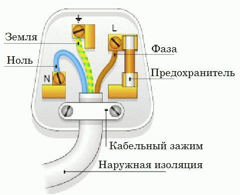
230 volt UK plug
In each case, the common wire will be zero. Color does not play a decisive role. Although according to the norms, modern cables are equipped with painted insulation
Please note - if the house is equipped with grounding, there will be at least 5 cores at the entrance. The shield body is planted on a yellow-green
The neutral wire will serve to drain the operating current from the devices (closes the circuit). Merging branches on the consumer side is not allowed. Here are three rules that help you figure out the access shield (note, according to the rules, the tenant should not show his nose there at all - they warned):
- The circuit breaker breaks the phase. There are two-pole models, they are used relatively rarely for rooms with special danger (bathroom). Therefore, by the position of the wire, it will be possible to say: this is a phase. Then you can cut down the machine, ring the vein on the side of the apartment. Definitely gives the position of the phase.
- The voltage between the neutral wire, any phase is 230 volts. Based on the key feature, we select a vein that gives the indicated difference to another. The spread between the phases is 400 volts. Percentage values are 10 higher, Russian chains are trying to meet European standards.
- With current clamps, we measure the values on the conductors. For each phase there will be a certain value, the sum of which (by three) must flow back into the network through zero (or a suitable phase). Grounding is rarely used, the current here will be close to zero if the branches are evenly loaded. The place where the value is the most is traditionally the null conductor.
- The ground terminal of the switchboard is visible. The sign will help to find the neutral wire in houses with NT-C-S. In other cases, grounding is supplied here.
Where did zero come from and how does it happen
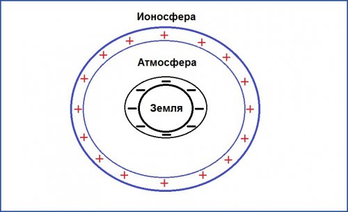
If we consider the planet Earth from the point of view of electrical engineering, then it is a spherical capacitor. It has three elements:
- The earthly firmament, which has a negative potential.
- The ionosphere is the layer of the atmosphere that receives and partly scatters solar radiation. It has positive potential.
- A gaseous atmosphere that has dielectric properties and plays the role of a lining.
The potential difference between the plates of this global capacitor is 300 thousand volts. It decreases as you get closer to the surface. So, at a height of 100 meters, its value is 10 thousand volts.
Why do we consider the potential of the Earth equal to zero, because in fact it has a completely material value, albeit with a negative sign? This question is worth asking the scientists of the 18th or 19th centuries, who laid the foundations of electrical engineering.
For example, the English physicist Michael Faraday. So it was more convenient for them to measure the intensity of the electromagnetic field - to take the Earth as a reference point (zero). This technique is used in many branches of science. For example, in thermodynamics. It takes as absolute zero the temperature at which the movement of electrons in the atomic structure of any substance stops.
This is the so-called Kelvin scale, which differs from another temperature measurement system - it was proposed by Anders Celsius - by 273 degrees with a minus sign.
So, electric zero is a conditional concept that is used in relation to any object with a negative potential. It can be obtained in three ways:
- Having joined the earthly firmament, which is why the concept of "grounding" came about.
- The crystal lattice of all metals has a negative charge of various sizes, which determines the degree of their electrochemical activity. Therefore, it is enough to join a metal object of large mass and volume. The last two conditions are mandatory, since the body must have an electrical capacity comparable to that of the Earth. This is called working grounding.
- By connecting the conductors to the alternating current flowing through them so that at a common point the sum of their vector addition is equal to zero (the so-called star circuit), which is why it was called neutral.This is the basis of the technique called zeroing in electrical engineering.
Why do we need zero in electricity
Zero closes the circuit. Without this wire, there can be no electric current in the circuit, which gives power to power household appliances. In fact, the neutral wire is the ground.
Where does zero come from in the power grid
It starts its zero from a complete transformer substation 6 (10) / 0.4 kV, where the transformer is connected to the ground loop with its zero bus. Initially, it is the earth that is a conductor with zero potential, and that is why many people confuse zero with earth. The overhead line (overhead power line), leaving the PTS, has 4 wires - 3 phases and zero, which at the beginning of the line is connected to the zero of the transformer. Throughout the overhead line, re-grounding is performed through one support, which additionally connects the zero of the line to the ground, which gives a more complete connection of the “phase-zero” circuit so that the end consumer has at least 220V in the outlet.
 Phase, zero and earth in the wire
Why do we need zero
The main purpose of the neutral wire is to close the circuit to create an electric current for the operation of any electrical appliance. After all, in order for the current to appear, a potential difference is needed between the two wires. Zero is called so because the potential on it is zero. Hence the voltage level 220V - 230V.
Basic concepts.
Power
current—
scalar physical quantity equal to
the ratio of charge passing through
conductor, by the time for which this
charge has passed.
where I—
current,q—magnitude
charge (amount of electricity)t—
charge transit time.
Density
current—
vector physical quantity equal to
the ratio of the current strength to the area of the transverse
conductor section.
where j—density
current, S— square
conductor section.
Direction
current density vector coincides with
direction of travel is positive
charged particles.
Voltage — scalar
physical quantity equal to the ratio
complete work of Coulomb and third-party
forces when moving positive
charge on the plot to the value of this
charge.
whereA—complete
the work of third-party and Coulomb forces,q—
electric charge.
Electrical
resistance—
physical quantity characterizing
electrical properties of a circuit section.
wherep—
conductor resistivity,l—length
conductor area,S—square
conductor cross section.
Conductivitycalled
reciprocal of resistance
whereG—conductivity.
Interference sources on the ground bus
All interference affecting cables, sensors, actuators, controllers and metal automation cabinets, in most cases, also flows through grounding conductors, creating a parasitic electromagnetic field around them and a noise voltage drop on the conductors.
Sources and causes of interference can be lightning, static electricity, electromagnetic radiation, "noisy" equipment, power supply network 220 V with a frequency of 50 Hz, switched network loads, triboelectricity, galvanic couples, thermoelectric effect, electrolytic processes, movement of a conductor in a magnetic field, etc. There is a lot of interference in the industry due to malfunctions or the use of non-certified equipment. In Russia, the level of interference is regulated by standards - GOST R 51318.14.1, GOST R 51318.14.2, GOST R 51317.3.2, GOST R 51317.3.3, GOST R 51317.4.2, GOST 51317.4.4, GOST R 51317.4.11, GOST R 51522, GOST R 50648. At the design stage of industrial equipment, in order to reduce the level of interference, a low-power element base with a minimum speed is used and they try to reduce the length of the conductors and shielding.
Phase and zero concepts and difference
There is such a thing as stress. This word means the degree of electric field strength at a given point or circuit.Otherwise, it is called potential. In very simple words, it is a kind of piston that gives impetus to the electrons so that they pass through the wires and light the bulb in the chandelier.
In the common circuit (phase zero), the one that comes to the chandelier or socket, there are two wires. One of them is the phase. It is this wire that is energized. A phase in electrical engineering is comparable to a plus in a car - this is the main power supply for the network.
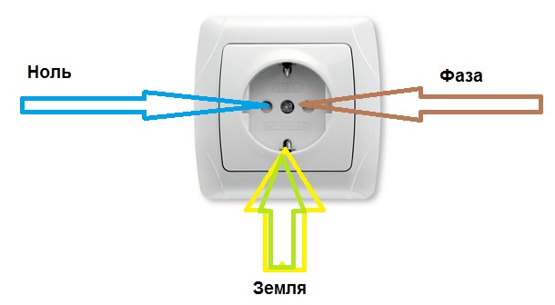 Phase, zero, earth in the outlet
Zero is a wire that is not energized (this is exactly how zero differs from phase). It is not overloaded during the power take-off, but, nevertheless, an electric current also flows through it, only in the opposite direction to the phase. In the absence of voltage, it is safe in terms of electric shock to a person.
Grounding conductors
The most common color designation for grounding insulation is combinations of yellow and green. The yellow-green coloring of the insulation has the form of contrasting longitudinal stripes. An example of a grounding conductor is shown below in the image.

Yellow-green coloring of the earth electrode
However, occasionally you can find either completely yellow or light green color of the insulation of grounding conductors. In this case, the letters PE can be applied to the insulation. In some brands of wires, their yellow and green color along the entire length near the ends with the terminals is combined with a blue braid. This means that the neutral and ground in this conductor are combined.
In order to distinguish between grounding and grounding during installation and also after it, different colors are used to insulate the conductors. Grounding is carried out with light blue wires and conductors connected to the bus marked with the letter N. All other conductors with insulation of the same blue color must also be connected to this zero bus. They must not be connected to switch contacts. If sockets with a terminal marked with the letter N are used, and at the same time there is a zero bus, there must be a light blue wire between them, respectively, connected to both of them.
How to distinguish phase, zero, ground
The easiest way to determine the purpose of the conductors is by color coding. In accordance with the standards, the phase conductor can have any color, the neutral - blue marking, the earth - yellow-green. Unfortunately, when installing electricians, color marking is not always respected. We must not forget the likelihood that an unscrupulous or inexperienced electrician can easily mix up the phase and zero or connect two phases. For these reasons, it is always better to use more precise methods than color coding.
You can determine the phase and neutral conductors using an indicator screwdriver. When the screwdriver comes into contact with the phase, the indicator will light up, as an electric current passes through the conductor. Zero has no voltage, so the indicator cannot light up.
You can distinguish zero from the ground with the help of dialing. First, the phase is determined and marked, then the continuity probe must be touched to one of the conductors and the ground terminal in the switchboard. Zero will not ring. When touching the ground, a characteristic sound signal will be heard.
If you find an error, please select a piece of text and press Ctrl+Enter.
Zero conductor
The neutral conductor or, as it is also called, the neutral performs a simple but important function. It equalizes the loads in the network, providing a voltage of 220 volts at the output. Eliminates phases from jumps and distortions, neutralizing them. Not surprisingly, its symbol is the letter n - derived from the English word Neutral. And the combination of designations n, l in electrics always go side by side.
In the switchboard, all cables of a given color are grouped on one, zero bus with the corresponding letter abbreviation. The sockets also have the necessary markings.
Therefore, the master will never confuse where to attach a special zero contact.
Such marking, the principle of operation is applicable to both single-phase and three-phase networks.
Phase and zero in electrics
Electricity appears as a result of the ordered movement of charged particles in wires - electrons. These electrons are born in huge power plants - such as, for example, the Volgograd State District Power Plant (hydroelectric power plant), the Novovoronezh Nuclear Power Plant (nuclear power plant) and many others in our country. Further, through very thick wires, this energy is transmitted to intermediate substations (as a rule, these are located on the periphery of cities), and from them to local transformer substations (complete transformer substation), which are in almost every yard.
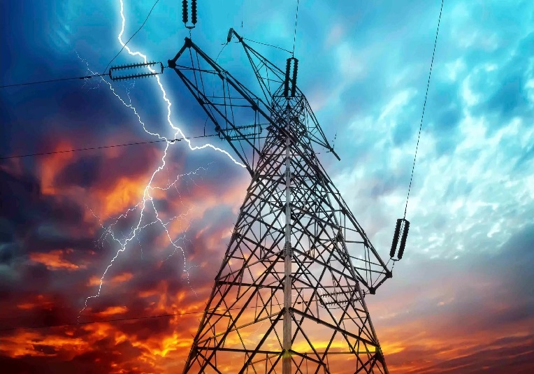 Power line
Voltage levels in such networks range from 750,000 volts to 380 volts at the final PTS. And it is the latter that make it so that 220V appears in the outlet of an ordinary house. It would seem that everything is simple, but! The socket has two wires. And from the lessons of physics, everyone knows that in an electrician there is a “phase” and “zero”. These two words give us light, heat, water, gas and much more that we use every day. Now in order.
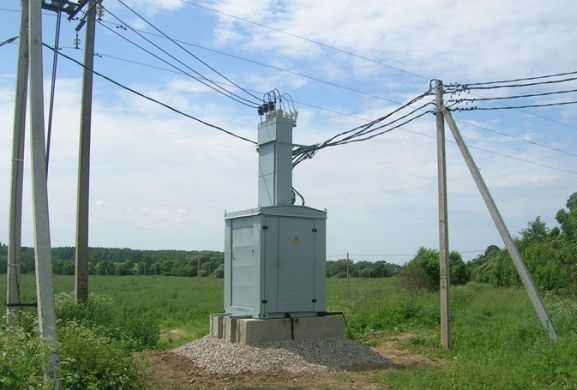 KTP
KTP
Ground voltage is greater than phase voltage. So it is necessary
Private house. I made grounding - 15m armature 10kA + 2m strip in the ground, the rest on the surface. Zero-phase voltage 216 V, earth-phase voltage 222 V, i. more. Is this normal? If ground-zero matters, the tester shows 3 V.
The quality of grounding is determined by the resistance.
Well, in general - at zero, the potential from zero is usually excellent)) But this is not normal. Make a re-grounding of zero on the input support - and then there will be zero at zero
as if we had a network with a grounded neutral by default. So land safely before entering the house
——————Long live temporary difficulties!
If the author is very worried about distortions and really wants symmetry, you can put an isolation transformer at the input (I can’t imagine the price) and make your own power supply system, preferably with zero, separate from grounding.
In general, there are problems with the RCD
I correctly understood that if I connect zero to the ground after the counter, then these 3 V will wind up the counter around the clock? Or slow down?
------Guys let's be friends! (With)
The old counter most likely will not react to this in any way. But the new electronic one is likely to count.
I opened a similar topic too. I decided not to do the ground. I limited the RCD. Everything works.
Yes, I’m not going to do this, at least because of the 3 V on the case of any device. Another question: RCD does not care which side to the network, which to the meter? Zero is marked as zero there and the phase is marked with the numbers 1 and 2.
------Guys let's be friends! (With)
By the way, if one wire from an electrical device is to a grounded pin, and the second to a phase, it will work at the expense of Chubais.
------temporary difficulties
Through the counter from the phase will still flow. Even to zero, even to the ground. And such a mountain of economists must be grounded alive! How many times, working in apartment buildings received from heating and plumbing.
------Guys let's be friends! (With)
not in the case of a detached house.
------temporary difficulties
I won’t say about today, but about two years ago I worked with a new counter. Province, sir ..
------temporary difficulties
even 2 years ago - You surprised me very much, well - here you really need to look at which province ...
…
In order not to produce topics, can an RCD be put on an unstabilized line at all? There are differences from 180 to 230.
in theory, it is possible. it does not follow the voltage, but monitors its differences. those. if an equal amount of energy passes through zero and phase, it does not work. In the event of a leak, a breakdown to the ground, and the like, the balance is disturbed and the circuit breaker is triggered.
And it won't always kick out?
you have a purely rural situation in terms of voltage drops, maybe one of your comrades will tell you.Ouzo is a capricious thing - it leaks a little and knocks out - the wiring must be of high quality. It works spontaneously for me 2-3 times a year, I don’t know the reasons, I just turn it on and that’s it.
I'm talking about the cottage and asking)
In my village, drops of 180-230 ouzo work normally, a clear response is only for a leak, there have not been any false ones in a year.
I spoke with two electricians - both said that they would knock out, but now I understand with my head that this should not be, because it was quite rightly noted:
Yes, it's clear which is better! Nobody argues. Will there be constant triggering on the dacha line? Otherwise, it just torments you and you have to throw it away - money down the drain!
If I may. I have all the Legrand assault rifles. The line is 3-phase.
We started from the “dirty” zero, reached the RCD ... What is the connection? Three volts at zero relative to the ground is simply nothing for the countryside. My neutral wire has a re-grounding to the reinforced concrete armature of the support from which the entry into the house was made. A three-phase RCD knocked out only once in four years, during a thunderstorm. Personally, for me, it is better to allow false positives than one accident.
Reinforced concrete stepchildren, the poles are already rotten, the transformer is breathing heavily.
How is ouzo amperage selected? 25 is not enough?
I have a dedicated 5 kW, respectively, an introductory machine of 25 A, the ouzo should switch the same current.
And I have a 40 A automatic ...
It is better to change IEC to something more decent, IMHO.
Chinese crap.
Phase in electricity
Do you know about power plants? Everywhere the principle of its occurrence is the same: the rotation of the magnet inside the coil leads to the fact that it appears. This effect is called EMF, or electromotive force of induction. The rotating magnet is called the rotor, and the coils attached around it are called the stator.
An alternating voltage is obtained from a constant when the latter is bent along a sinus, as a result of which its positive, then negative value is achieved.
So, the magnet is set in motion, for example, due to the flow of water. When the rotor rotates, it changes all the time. Therefore, an alternating voltage is created. With three coils installed, each of them has a separate electrical circuit, and inside it the same variable value appears, where the phase of the voltage is shifted around the circumference by one hundred and twenty degrees, that is, by a third relative to the one located nearby.
Why is nulling necessary?
Mankind actively uses electricity, phase and zero - the most important concepts that you need to know and distinguish. As we have already found out, in phase electricity is supplied to the consumer, zero drains the current in the opposite direction. It is necessary to distinguish between zero working (N) and zero protective (PE) conductors. The first is necessary to equalize the phase voltage, the second is used for protective zeroing.
Electrical networks with an isolated neutral do not have a zero working conductor. They use a neutral ground wire. In TN electrical systems, the working and protective neutral conductors are combined throughout the circuit and are marked PEN. Combining the working and protective zero is possible only up to the switchgear. From it to the end consumer, two zeros are already launched - PE and N. Combining zero conductors is prohibited for safety reasons, since in the event of a short circuit, the phase will close to neutral, and all electrical appliances will be under phase voltage.
Conclusions Grounding Rules
Radical methods for solving grounding problems:
- Only use I/O modules with galvanic isolation
- Do not use long wires from analog sensors
- Place input modules in close proximity to the sensor and transmit the signal digitally
- Use sensors with a digital interface
- In open areas and long distances, use optical cable instead of copper
- Use only differential (not single) inputs on analog input modules
More tips:
- Use a separate copper bus ground within your automation system by connecting it to the building protective earth bus at only one point
- Connect the analog, digital, and power grounds of the system at only one point. If this is not possible, use a copper bar with a large cross-sectional area to reduce the resistance between different ground connections.
- Make sure that when installing the grounding system, a closed loop is not accidentally formed.
- If possible, do not use ground as a voltage reference level when transmitting a signal.
- If the ground wire cannot be short, or if for structural reasons it is necessary to ground two parts of a galvanically coupled system at different points, then these systems must be separated by galvanic isolation
- Circuits that are galvanically isolated must be grounded to avoid the accumulation of static charges.
- Experiment and use devices to assess the quality of grounding. Mistakes are not immediately visible
- Try to identify the source and receiver of interference, then draw the equivalent circuit of the interference transmission circuit, taking into account parasitic capacitances and inductances
- Try to isolate the most powerful interference and defend against it first
- Circuits with significantly different power should be grounded in groups, in each group - blocks with approximately equal power
- Ground conductors with high current must be routed separately from sensitive conductors with a small measuring signal
- The ground wire should be as straight and short as possible.
- Do not make the signal receiver bandwidth wider than necessary for reasons of measurement accuracy.
- Use shielded cables, ground the shield at one point on the signal source side at frequencies below 1 MHz and at several points at higher frequencies
- For particularly sensitive measurements, use a "floating" battery pack
- The most "dirty" earth is from the mains power supply. Do not connect it to analog ground.
- Shields must be insulated to prevent accidental closed loops and electrical contact between the shield and ground.