How balancing is done
Depending on the model of the flowmeter, after installation and pressure testing of the heating system, they are set to their original position "open". For appliances that do not have a built-in valve with speed graduation, the additional valve is set to the "fully open" position, and the system is balanced after start-up.
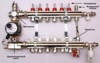 Standard manifold assembly
In combined models, it is possible to preset the number of complete turns of the valve. Each revolution reduces the clearance by a fixed amount.
First, the volume of coolant required for each circuit is calculated and its percentage is determined relative to the total volume of coolant for the entire system. In accordance with these indicators, the initial position of the flow meter valve head on each circuit is set.
The final adjustment is made during operation. At the same time, they proceed from real temperature indicators and feelings of comfort.
Step by step instructions for installation and adjustment
The rotameter is installed strictly vertically. In order for the liquid level in the flask to be accurate, the collector itself is also mounted according to the level. If the manifold pipe is installed crooked, the temperature control will not be correct.
Since finishing work often occurs after the installation of the collector, it is necessary to protect the assembly and its components from possible damage. The best option is to make a niche in the wall for it or a special cabinet.
Installation and adjustment:
- Using a wrench, screw the flowmeter into the process inlet of the return line of the collector;
- By turning the membrane (flask) counterclockwise, open the pressure meter;
- Remove protective factory ring;
- Turn the brass body ring clockwise to the desired pressure. This is balancing the flow rate of the energy carrier. The float on the scale will indicate the set value;
- Close the brass ring with an overlay. This must be done in order to avoid damage to the device, especially if the water floor heating unit is not closed in a niche or cabinet;
- Check system operation.
During operation of the assembly, the flask remains open so that the level of the water float can be seen. If balancing is needed during operation, the membrane simply rotates in the right direction.
Installation and adjustment
According to the manufacturer's instructions, the rotameter is connected to the return manifold, but there is an option to install the device on the supply.
The main requirement for the installation of the device is its vertical location. This setting allows you to determine the exact value of the liquid level in the flask. Therefore, the comb must be placed strictly horizontally in level.
The rotameter is connected by screwing into the appropriate socket on the manifold. The kit includes a sealing ring and a union nut. It is not necessary to additionally seal the device with sealant or other materials.
The workflow of the coupled circuit collector - collector and flow meter must be fully automated. Therefore, a temperature sensor is additionally connected to the system. With such a scheme, the system, when the specified temperature regime of the coolant is reached, blocks its full or partial access to the circuits.
Installation of underfloor heating flowmeters
The entire installation process and adjustment of the rotameter for underfloor heating is performed in the following sequence:
- The flow meter must be screwed into a technological hole specially designed on the collector. The device is installed with a key in a strictly vertical position.
- Turn counterclockwise and remove the transparent flask located in the upper part of the flowmeter body.After that, it is necessary to remove the ring, which is installed for protection by the manufacturer. Then put the cap with markings back on.
- Turn the housing clockwise to the required pressure level indicator. This action is a balancing of the coolant flow rate. In this case, the set value should be displayed on the scale.
After such actions, it is necessary to check the working process of the entire floor heating system. During the operation of a warm floor, do not close the flask on the flow meter. The scale must be constantly in sight, as sometimes it becomes necessary to balance during the operation of the heating equipment.
According to the technical rules, identical laying of several circuits, including their length, should be carried out. Otherwise, even the use of a collector with a rotameter will not give a positive result, and the system will not function correctly.
Return water temperature setting
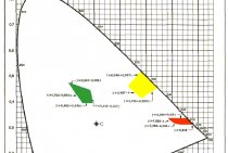
The flow rate of the coolant, the power and the temperature difference between the supply and return pipelines are interconnected. If the coolant flow rate in the loop is reduced, then the temperature difference will inevitably increase. It is by this dependence that the correctness of the setting can be determined.
In the event that all loops of the underfloor heating will have the same temperature difference between the supply and return pipelines, this will mean that in all loops the coolant flow rate corresponds to the current power. And since the temperature in the supply manifold is the same for all loops, the temperatures can only be equalized in front of the return manifold.
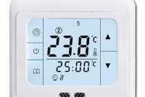
It is more convenient to take temperature readings with the help of special thermometers that are mounted between the pipe and the return manifold.
The reference temperature is measured on the longest loop. After that, all other valves are adjusted depending on the deviations from this temperature. If the temperature on some loop is lower than the reference one, then the flow rate in this loop is also low. Therefore, the valve of this loop must be slightly opened. If the flow rate of the coolant is higher than the reference, then the valve must be closed. After adjustment, you must wait half an hour, and then repeat the operation. And so repeat until the temperature of the coolant in all loops in front of the return manifold is equal.
Ideal manifold design
This collector group is considered the best system, in which the supply manifold is equipped with a rotameter, and a thermostat is placed on the return manifold. Such a system will make it possible to direct a sufficient amount of heat carrier into each circuit, and the return collector of such a system will close and open the circuits as the water cools.
It must also be said that the system can be improved with an automated Mayevsky crane, which is placed on the supply manifold, for its part, it must be connected to a circulation pump with a bypass valve.
It will work like this:
- Mayevsky taps will remove air from the system, which interferes with its good work;
- If it gets warmer outside, external water thermostats will close the circuits, and the bypass valve will reduce the increased pressure from inside the system.
Talking about how the flow meter works underfloor heating, you need to make an amendment: there are three types of rotameters:
- The measuring rotameter is installed simultaneously with the valve, which changes by hand, depending on the measured readings;
- The adjusting rotameter controls the amount of incoming heat carrier;
- The 3rd type combines the two previous ones, but it also has a very high cost.
Flowmeter functionality
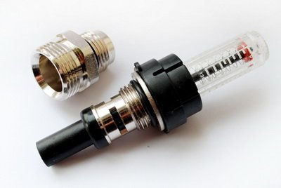
A rotameter or, if we give a full definition of this unit, a float rotameter, at first glance, is an ordinary mechanical device.The design of the product is based on a plastic case (there are brass models), inside of which a polypropylene float is placed. The case is equipped with a transparent flask, on which a marking scale is applied. Moving the float up and down inside the device indicates a certain value on the scale, which can be used to judge the volume of coolant circulating in the piping system - is it enough for the full operation of the heating circuits.
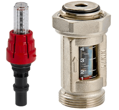 Traditional flow meter for underfloor heating collector in various versions: on the left - in a plastic case, on the right - in brass.
From the point of view of theory, the heating system can work without this device. In this case, you will have to manually adjust the volume of water entering the circuit, based on personal feelings when the air temperature in the room changes.
- separate contours of the water floor will be supplied with a heat carrier without taking into account the characteristics of the room, as a result of which the temperature values of the floor surface of heated rooms will differ;
- the consumption of the energy carrier used to operate the heating devices (electricity or gas) will be increased.
For example, you plan to heat the bathroom and the children's room at the same time. An autonomous gas boiler will heat water for the bathroom and the nursery in the same way, in the same temperature regime. However, the bathroom is smaller and will require less boiler water to heat it than to supply a warm floor in a nursery. It is possible to achieve an optimal supply of heat carrier for underfloor heating in each room using a flow meter. Therefore, due to the operation of this device, it will be possible to achieve individual temperature values \u200b\u200bfor comfort in the bathroom and children's room.
Evaluating the operation and principle of operation of the device, we can draw the following conclusions:
- the device functions completely autonomously, without requiring additional power sources;
- the principle of operation of the flow meter allows you to create the optimal flow of coolant for heating circuits, significantly reducing the energy consumption of heating devices;
- the design of the device provides visual control over the amount of water in the pipelines;
- the collector, together with flow meters for underfloor heating, greatly facilitates the control over the operation of the entire system, is easy to install and unpretentious in maintenance.
Good flow meter
In the store you can come into contact with a large selection of various rotameters, thanks to this, in order to find a good copy, you can look for it according to the properties listed below:
The flowmeter must have a good body without chips and protrusions
The body material is brass, but it is covered with nickel on top.
The internal spring of the rotameter must be made of stainless steel.
Polycarbonate material is an excellent example of a material for a translucent flow meter bulb, because this material will withstand high temperatures, as well as some physical influences.
It is unrealistic to determine this in a store, thanks to this you will need to trust the manufacturer and pay your own attention to the indicators: the device must keep the temperature up to 110 ° C, and also a pressure of 10 bar.
The largest throughput of the rotameter should not be less than 2-4 cubic meters per hour. The measuring scale must correspond to these indications.
The guarantee for such products is given a large, very often from 5 years.
Conclusion
The manifold for underfloor heating with flow meters makes it possible to control the flow of the heat carrier, which ensures the optimum temperature of the floor in each room connected to this circuit. A similar version of the device of the underfloor heating system additionally saves money, because you spend less energy on water heating.
Underfloor heating from a 2-circuit boiler.
Hello. Has anyone had any experience with diagonal manifolds?The fact is that I mount heating (radiation wiring) and warm floors. There are two collectors, one with flow meters for floors and one without for radiators. for floors it is clear that the entire flow is adjustable, but not for radiators. the question is if the collector for radiators connect the supply pipes diagonally and not by the one-sided method, as usual, will the radiators warm up evenly. in fact, this is the same two-pipe in the same direction and not a dead-end type. I mean maybe this way the pressure will be more or less evenly distributed over the radiators
Is this some kind of diagonal radiator connection? If you look at everything as a whole, then I think your idea will work, but you need to calculate it. Isn't it easier to balance?
it is impossible to balance it out. Butterfly ball valves are on radiators.
I do not rule out your idea. If it is not possible to balance then screw the flowmeters into the supply manifold or try experimenting with your method.
r072, you're digging in the wrong place. If a diagonal connection is not justified by convenience, do not bother.
I did not notice this game. And yes, it's crazy.
game on the hunt, you will notice, but my question was an edge on hydraulics. I'm not interested in convenience, but I installed a collector without flow meters 12 out. they said so. 12 branches are all different in length as well as radiators in sections. each circuit has its own resistance, as a result of which my radiators heat differently and I was tormented by their cranes. so I'm asking about the diagonal inclusion of collectors and not the one-way method as usual. for example, many turn on a radiator of 12 sections using the side one-way method, then 3-4 fins do not heat up, they begin to screw the tube at the bottom of the radiator up to section 8 so that the liquid cannot go back from the top supply through the near sections, as a result of which pressure is transferred to the far sections, although it was possible just connect it diagonally and the whole question. only apparently not everyone likes this arrangement of cranes. so in my case, although I’m not strong in this, I’m just interested in your specialists, maybe someone has already done this or knows whether such an option will work or not, an exact answer is needed and if not, then why not. in fact, this is the same two-pipe system of the associated direction. if you draw this two-pipe on a sheet and assemble it into an accordion, the same collector turns out only long branches, the person who answered earlier more or less understood the essence
The appearance of the problem
First of all, you need to analyze a specific example of the appearance of such a problem and its consequences:
- You mount contours underfloor heating in the bathroom, guest room and kitchen;
- They are connected to the same collector;
- The area of the bath, kitchen and guest room is frankly different, thanks to this, the length of the contour underfloor heating will vary in any room, naturally the flow rate of the heat carrier (water) will be completely different.
It is necessary to say what this will lead to. Short heating rings have less hydraulic resistance, due to this, the water in them moves much faster than in long circuits, which results in a temperature difference in the premises at the same temperature of the heat carrier supplied from the collector.
An example of a solution to the problem, on which we will analyze the principle of correction, is a primitive wall-mounted radiator. If you connect radiators with different number of sections and pipe lengths to one collector, then the problem described above will appear (read: “Heated floor collector diagram - how everything should work”).
The problem with radiators is easily solved, because the instructions say that by installing a thermostat on each battery, you will be able to control the quantitative flow. In most cases, the thermostat is a traditional valve. Akin to the problem is solved with the underfloor heating system.
Solving the problem with underfloor heating contours
By connecting underfloor heating circuits to the same collector group, you can balance them in two ways:
- The first method involves creating even rings, but you can put several of them in one room, for example, you can put one heating ring in the bathroom, three in the guest room, and two in the kitchen. Similarly, the heating of all rings will be the same.
- If you do not want to create multiple rings in the same residential area, then there is also a solution for you. Heating circuits can be of various lengths, but they should be connected through a specialized device - flow meter for underfloor heating. flow meter or a rotameter is an association of balancing valves that limit the amount of heat carrier released into the system. You can see an example of a rotameter in the photo.
Finally
When operating a water heated floor, the flow meter bulb on the manifold must be accessible to visual inspection and, if necessary, maintenance.
Each water circuit connected to the collector is equipped with an individual flow meter.
The choice of the device model does not particularly affect the quality of heating and the functionality of the water floor system - if you follow the rules for installing and operating underfloor heating equipment, you can achieve the necessary indicators by installing any high-quality devices.
Water heated floor, as a rule, consists of several contours of plastic pipes. Hot water, moving through them, gives off its heat and returns through the return supply part of the system. The collector (comb system) of a warm water floor is designed to collect cooled water, mix and supply heated water. In other words, it is a node that controls the operation of the underfloor heating system.
To regulate the temperature, flow meters are provided in the collector. These devices control the flow of the coolant, in this case water.
Theoretically, it is quite possible to do without mounting a flow meter in the manifold. However, if you do not install this device, then:
- In different rooms, the temperature will be different;
- Overexpenditure of electricity for heating water in the system is possible;
- Different circuits will warm up unevenly.
A simple example can be given: a bathroom and a bedroom. A gas or electric boiler heats water equally for both the bath and the bedroom. But the bathroom is at least 3 times smaller than the bedroom. Accordingly, it will be hot in the bathroom and cool in the bedroom with the same water supply to the underfloor heating system. This situation is due to the fact that the total length of plastic pipes in the area is much larger in the bedroom. It is in order to regulate a comfortable temperature regime in the entire apartment that it is desirable to install such a device.
Principle of operation
 The device is installed on the outlets of the return manifold. When the set temperature in the manifold valve system is reached, the energy supply gap is narrowed or completely blocked. This principle of operation is possible with full automation of the system. To do this, the collector is equipped with a temperature sensor.
The flow meter itself consists of several parts:
- Frame;
- Transparent flask with a scale;
- Float.
Flask usually made of durable glass, the body can be plastic or brass. The float is located inside the flask, it serves as an indicator of the speed of the coolant. The flow meter is also called a float rotameter.
In the automatic collector of a water-heated floor, the balancing of the coolant flow is carried out using a temperature sensor. If the latter is not provided, then the rotameter can be adjusted manually.